CDEF. Laser CNC
|
One of the most efficient survival strategies for an apocalypse is
to keep a CNC machine around. It lets you build your own tools
and weapons (as long as the power grid is up, the shops are
selling raw materials, etc.)
The next few tasks are about controlling your Laser CNC to cut out shapes from sheets. Since there is only one instance of the real hardware for 30 teams, a special arrangement is employed to let everyone have a go: |

http://www.personal.psu.edu/users/s/t/ sts5035/Cnc-World.jpg |
- the first three of the four tasks are simulated
- real CNC slots are limited, requests are queued
- the actual material to cut is paper; the device is capable of cutting plastic, but cutting paper goes much faster allowing more cut requests for 24 hours
- for the 4th task, we accept submissions only until the end of the 22nd hour of the contest (07:00)
The hardware
The laser cut CNC can move a laser module over the workpiece on two axes (X and Y) in discrete steps. The output power of the laser can be controlled between 0% and 100%. If the laser is on, it starts burning the workpiece, which starts to smoke out at the given location. After transferring enough heat at a specific point, a thin workpiece burns through. Moving at a low speed while the laser is on results in a cut along that line.The CNC runs a tiny controller that interprets a sequence of instructions and program timers to guarantee synchronous operation of motors and the laser. There is a simple language called laser script for programming the controller, with two main features: setting the value of registers (syntax: register=value) and starting an interpolation (moving the laser to the end coordinates; syntax: start). The relevant registers are the following:
| name | function |
|---|---|
| x | current X coordinate (not writable) |
| y | current Y coordinate (not writable) |
| tx | target X coordinate |
| ty | target Y coordinate |
| dx | speed: divider for the X axis |
| dy | speed: divider for the Y axis |
| pwm | laser power |
| bd | brake delay |
| dd | drill delay |
Movements along the axes and delays (bd, dd) need to be synchronized. This is achieved by dividing motor steps and delays from a central timer generating ticks at about 35 kHz:
- STAGE 1: drill delay: if pwm is not zero and dd is not zero, set laser power to pwm, and load a counter with dd; decrement the counter each tick until it reaches zero; do not move the motors while doing this;
- STAGE 2: move: there is a counter for the X axis, which is loaded with dx on start, then in each tick the counter is decremented; when the counter reaches 0, a step in the right orientation along X towards tx is generated on the motor, x is updated and the counter is loaded with dx again; if x == tx, stop stepping in this direction else go on with STEP2 procedure;
- STAGE 2: the Y axis has a similar counter loaded with dy with the same rules, targeting ty; the two counters and motor steppings are rendered in parallel, until one of them reaches its target
- STAGE 2: if both targets (tx and ty) are reached, set motors in brake mode and move on to STEP3
- STAGE 3: braking delay: if bd is not zero, switch off the laser, load a counter with bd, decrement the counter in each tick; when zero is reached, set laser power to pwm again, insert 1 tick delay (for timing reasons) and proceed with the next command
The above procedure is called interpolation. We distinguish between two kinds of interpolation:
- the traveling interpolation: the laser is turned off (pwm=0), no cut is performed;
- the cutting interpolation: the laser is turned on (pwm is larger than zero, the workpiece is being cut during the interpolation.
An example laser script:
dd=12
bd=23
dx=19
dy=11
pwm=20
tx=10
ty=14
start
Assuming the current x;y coordinates are 4;6 and the laser is turned off (pwm=0), the above script will produce the following step pattern:
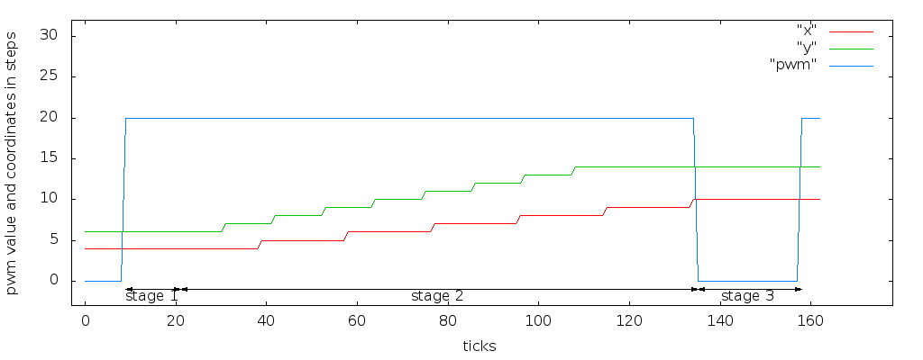
Note: the actual values in this example are invalid on the real device (speeds too high) and are chosen for simpler visualization.
The slope is not calculated properly in this example: y reaches its target (14) much sooner than x reaches 10. This will result in cutting two line segments, a slope and a short segment aligned with the X axis. However, after start finishes, the new x;y coordinates are tx;ty (10;14). For the braking delay (bd), the laser is turned off and the original power is restored after the delay, which will leave the laser turned on at power 20 after the cut.
For traveling between cuts, the laser shall be turned off to avoid cutting across the workpiece. This can be done by inserting a pwm=0 before the next start command. Since laser power is restored after the braking delay, there will be a very thin spike (a blink of the laser) between a cutting interpolation and a traveling interpolation. This spike is so narrow that it will not affect cut quality.
The drill delay (dd) is provided for two reasons: some material can be cut better when starting from an edge. By drilling a hole before starting the cut, the cut is always started from an edge. When cutting a continuous series of line segments, only the first line requires a non-zero dd; drilling between such lines will not just slow down the process but may result in small glitches where lines are connected.
The second delay, braking delay (bd) is provided as a compensation for the mechanical inertia of the system. An ideal CNC would feature motors strong enough to speed up and slow down the laser module within a fraction of a single step. The real device is not that strong. In the worst case if the laser module is moving very fast in one direction and the motors start moving at a high speed in the other direction, the mechanics may miss steps during the direction change. The firmware will control the motor to rotate N steps in the opposite direction of the current movement but it will stay in place only slowing down or stopping the movement. The firmware will not know about this error and will assume the new coordinates. This sort of inaccuracy sums up after multiple direction changes. To avoid this problem, the braking delay is implemented to allow the mechanics to slow down while motors are trying to keep the laser module in place. Doing this between each two interpolations avoids the rapid change of direction.
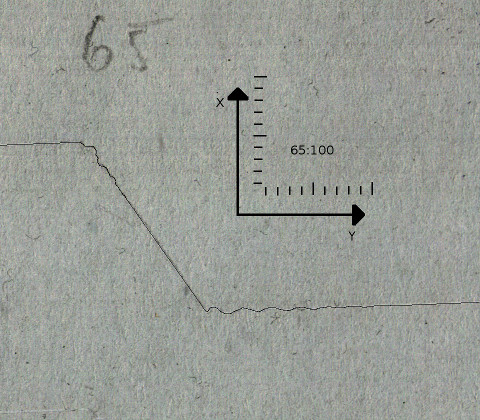
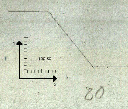
Note: not only braking but accelerating the module also takes considerable effort for the motors. This may produce tiny oscillations, especially along the X axis, during both acceleration and braking. There is no delay inserted for acceleration as using a sufficient bd will avoid the inaccuracy. Below is a photo of a typical oscillation produced by moving at constant speed along one axis and rapidly speeding up/stopping along the other axis without brake delay.
| 
|
| large oscillations | small oscillations |
| (scale is 10x10 mm; speed values for this test were beyond the recommended/allowed values and bd was 0; operating the device within the absolute minimum/maximum range will reduce oscillations to a nearly unnoticable level) | |
Choosing parameters which don't violate the absolute minimum/maximum values is required. Choosing values from the "safe value" column will work for any combination of parameters (e.g. cutting direction, previous state of the device). It is possible to optimize a set of interpolations for speed by using the "fastest value" column, but care should be taken to avoid inaccuracy. For example when cutting a series of line segments with only slightly differing angles, the braking delay can be decreased, but it should be set back to the safe value for stopping after fast travel.
| property (register) | unit | absolute minimum | absolute maximum | safe value | fastest value without error | comment |
|---|---|---|---|---|---|---|
| travel in direction X (dx) | div | 80 | 5000 | 110 | 108 | it is not possible to speed up to 80 directly; use a value >=108; using lower values may result in missed steps |
| travel in direction Y (dy) | div | 80 | 5000 | 110 | 108 | |
| cut in direction X (dx) | div | 80 | 5000 | 450 | 420 | refer to the cut test page; cutting a 10% slower than the maximum speed will not have visible affect on cut quality |
| cut in direction Y (dy) | div | 80 | 5000 | 450 | 320 | |
| brake delay (bd) | div | 1000 | 32000 | 2000 | 1500 | using a brake delay less than the safe value may result in missed steps when changing direction during travel |
| drill delay (dd) | div | 0 | 32000 | 4000 | 0 | drilling is not required for starting a cut on our current workpiece (dd should be 0); in case a single hole should be drilled at a specific coordinate, use the safe value without changing tx;ty |
| cut power (pwm) | 1 | 0 | 1023 | any | 1023 | 0 means laser is off; 1023 means laser is at 100% power |
| X coordinate (tx) | step | 0 | 3200 | 3190 | n/a | restricted by the physical geometry of the device |
| Y coordinate (ty) | step | 0 | 3200 | 3190 | n/a |
Units:
- div: divider used on the ~35 kHz timer
- step: number of steps along an axis
Laser script submissions are accepted only if absolute minimum/maximum ratings are not violated.
Laser script syntax
Each line of a laser script is a comment or instruction or empty line. Comments start with the hashmark (#). Empty lines may contain whitespace. Instructions are:- register = 16-bit integer written in decimal format
- start
- end
Different registers require signed and unsigned values. The start instruction will start an interpolation using the current register settings. No other instruction is executed until the interpolation is finished. The end instruction is the last instruction terminates the script. Explicit termination is required.
Some of the evaluators will require specially formatted comments to communicate meta-data (marking coordinates, tagging shapes).
Simulator, practice server
The first 3 problems are evaluated exclusively in the simulator. The simulator uses the firmware code to accurately reproduce the instruction interpretation and timing of the real device and somewhat-accurately simulates the behaviour of the workpiece. The output of the simulator is a png where black pixels represent untouched surface of the workpiece, white pixels represent cuts and gray pixels represent partial cuts or surface scratches. A text file with other properties of the simulation (total time elapsed, bounding box, etc) is also returned.The real workpiece (standard 80 gram black paper) may behave slightly differently, but it is guaranteed that safe values described in the table above will work with it.
A practice server is provided as a virtual task on the web based submission system. This task is not scored. Teams may submit laser scripts for simulation any time and the resulting png will be available to the team through a web page.
Using the actual hardware
The last task in this group is evaluated using real cutouts, but can also be used for testing the device. There is a queue of submitted cut requests. One team may only have only one submission in the queue. A request is either pending or being executed. While pending, the team may cancel the submission and submit a new script - to the end of the queue. Submissions being executed can not be replaced and the team has to wait until they are finished.The CNC is operated in batch of 1..4 submissions, in 30 minute cycles. In the best case a cycle will process 12 requests, but more often only 8..10. If all 30 teams have a submission in the queue, the last item will be scheduled in 2.5 to 3.75 cycles (75..112 minutes).
After the submission is cut by the laser, the team needs to visit the laser eval site and decide whether the submission was only for testing and should be discarded or should be tested and scored. The submission is removed from the queue only after it's been scored or discarded.
Because of the time constraints and properties of the task, long queues are expected by the 22nd hour. A team who starts submitting solutions for this task early will probably have much shorter turnaround times.
There is a test cut page on display at the laser CNC; it demonstrates sample cuts with different settings. We recommend careful evaluation of the sample cuts and solving at least the first two problems on the simulator before touching the real hardware.
Please note: the last submission for the actual hardware is accepted until the end of the 22nd hour of the contest - no submission is accepted in the last two hours to let accumulated submissions go through the system until the end of the contest.